
|
Slipstick V
|
| "It (the rocket) will free man from his remaining chains, the chains of gravity which still tie him to this planet. It will open to him the gates of heaven". Wernher von Braun. |

|
|
|
Slipstick V
|
| "It (the rocket) will free man from his remaining chains, the chains of gravity which still tie him to this planet. It will open to him the gates of heaven". Wernher von Braun. |
|

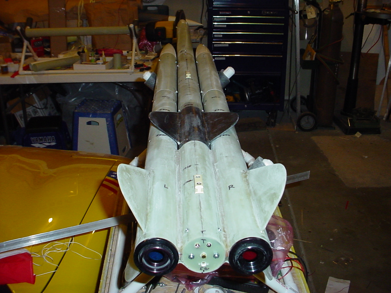
| Background: I had built Slipstick IV or "The Twins" (Micky and Ricky), as a two stage 3" dia rocket, 11 feet long weighing in at 15 lbs, which was designed to use two K700's in sequential staging. (see picture on left). It has a projected altitude of 15,000 feet AGL. It has flown twice so far. I wasn't quite comfortable with the length of the Twins, as it is a bit long and ungainly after you include 4 avionics bays and three deployment systems. I wanted to see if I could make everything a lot shorter by moving the 1st stage to the sides, like pods, but not have to worry about pod ejection, which isn't really a multiple stage, as far as having separate sequential staged rockets. Additonally, the pods generally use single deployment and can be scattered far apart from each other. |

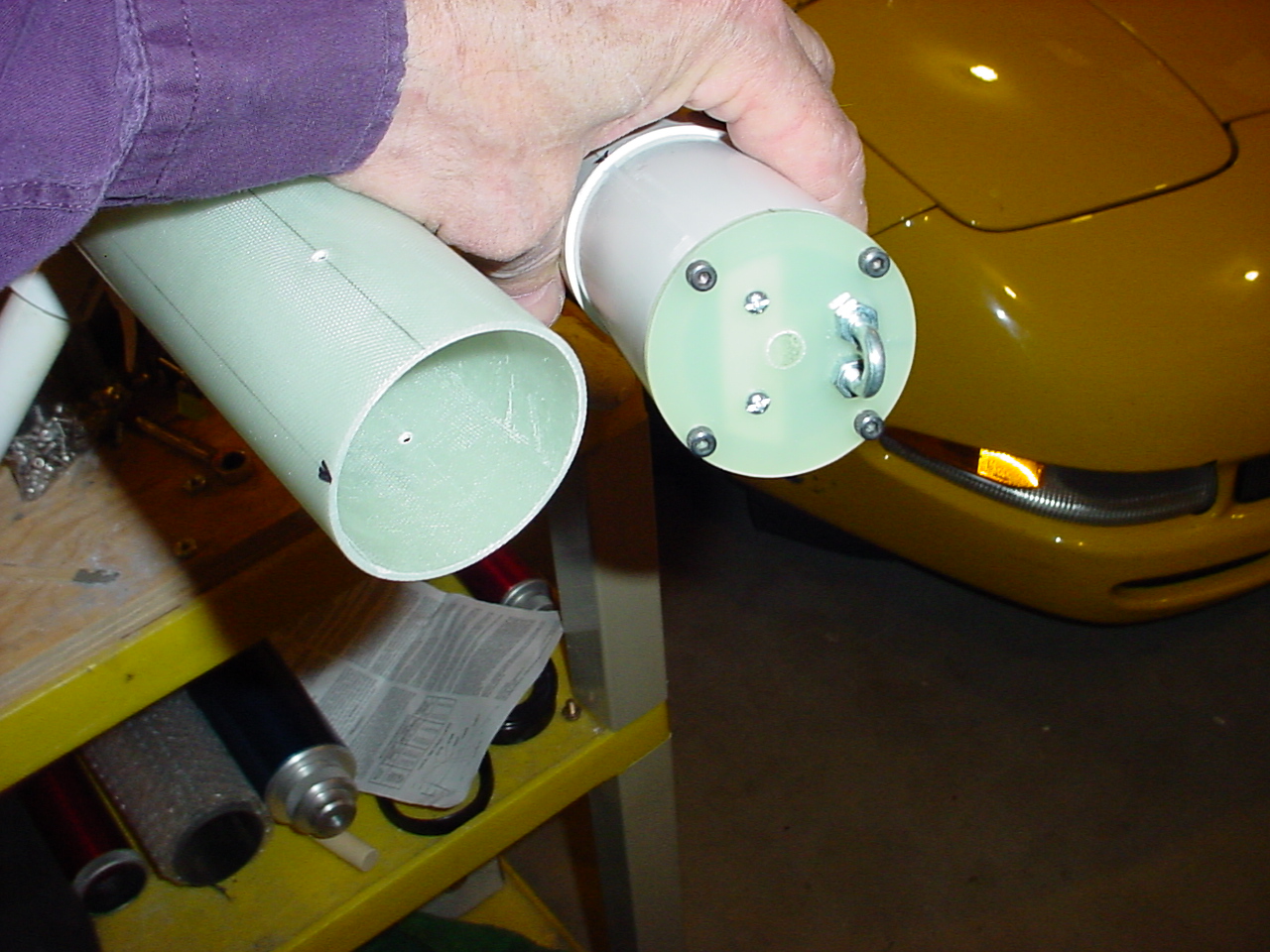
| Solution: A "Konshak Cradle Boosted Rocket" (tm). You heard the term first used here. It basically involves a pod-like arrangment for the booster, where two or more pods are all attached together around a central "Cradle" as part of a cluster, with the sustainer, mounted above and in-between the pods resting on the cradle. The benifit is that the cradle is a totally separate one-piece rocket section and the sustainer, once separated from the booster does not carry any extra weight. The Cradle Booster can utilize dual deployment as one pod handles the drogue, and the other the main chute. See the flight sequence on the left. |

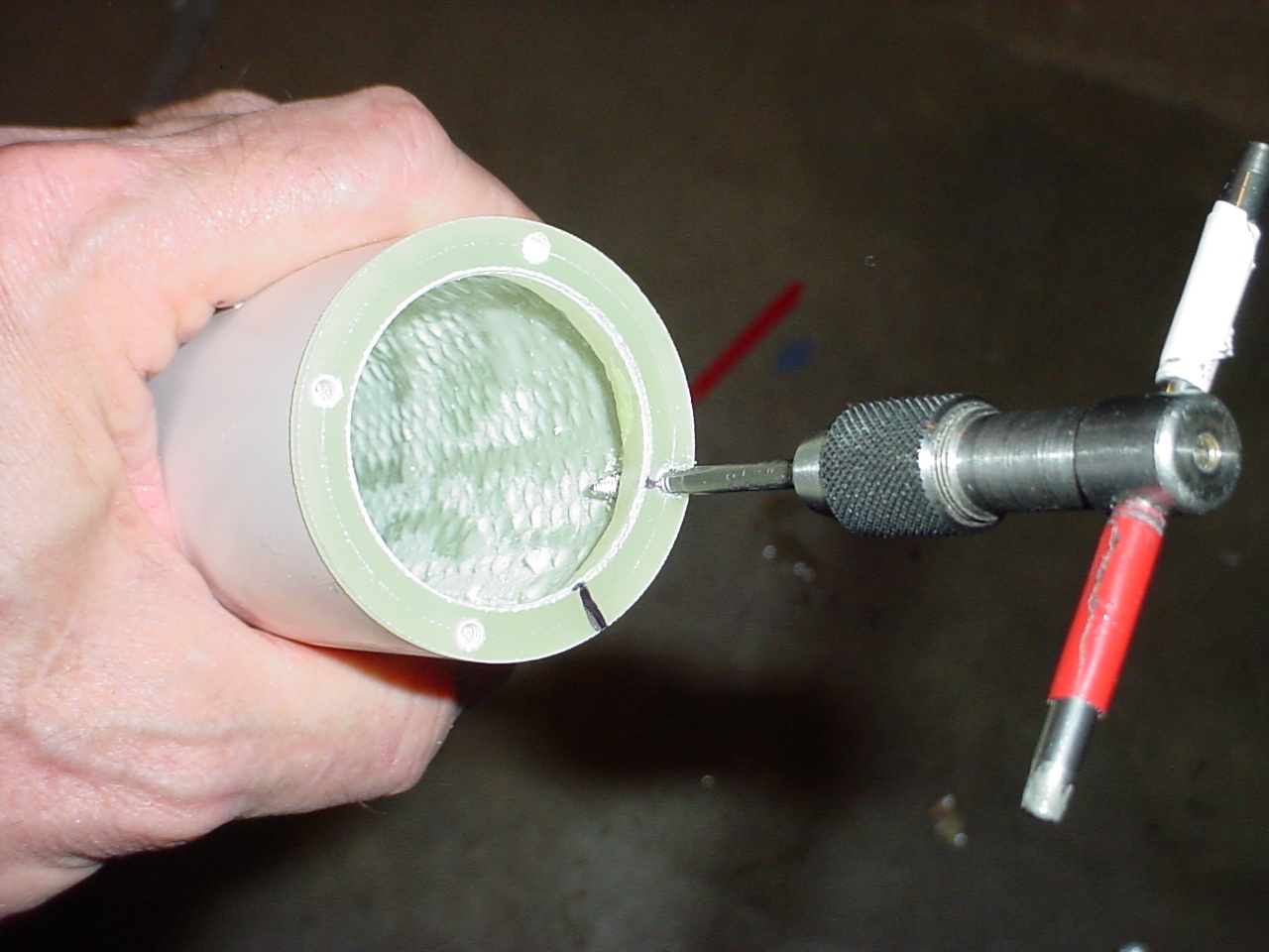
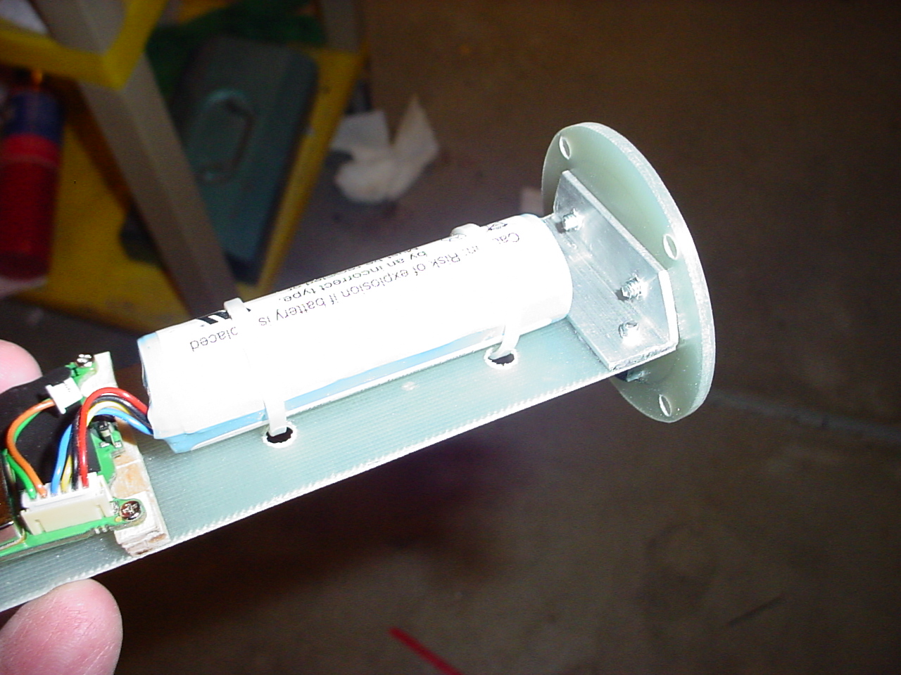
| Design: Slipstick V or "Gates of Heaven" in its present form consists of three 54mm in-line airframes, made from Performance Rocketry Little Dog Dual Deploy Kits (and extra parts). It is designed for three minimum diameter K motors (K700's or K660's), but it has 38mm options as well, which will be used for its fierst trial launch using 2each J350W in the cradle and J415W in the sustainer. The sustainer's motor extends out the bottom of the sustainer and is used as the coupler into the cradle. The motors are retained in the airframe at the forward closure end. Avionics are mounted in the nose cones of the Cradle pods (deployment) and in the center cradle airframe (sustainer ignition timer). The sustainer has a conventional avabay in the mid section for dual deployment and a DC20 (GPS) in the nose cone. Estimated altitude goal is to bust 30K. Download the entire Pro-E CAD drawing (5 pages). |

| Application: I received the three kits from Wildman Rocketry (two days before Christmas) with a Christmas discount so they ended up costing a total of $238 (w/shipping) for all three. This was my present from Becky so, although she let me get a head start on it (mounting the fins and cradle) I had to put it with the other presents for Christmas day. You'll noticed I put radii on the fin tips for my 'signature look' although one picture still shows them as a trapezodial. |
 Design Document |
 Mechanical Drawing |
 Flush Aft Closure |
 54mm K700W hardware |
 K700W hardware |
 38mm J350W hardware |
 Missileworks RRC2-mini Manual (same instructions for Public Missiles Co-Pilot) |
 Public Missiles Co-Pilot Manual |
 Perfectflite Mini Timer 3 Manual |
 PML Launch Lugs |


|
I had some down time up at our cabin (an internet and TV free zone),
but brought some model rocket
parts up with me. I made a model rocket version of the two-stage cradle
boosted rocket which would use three (3) BP Estes motors for the boost
(one to ignite the sustainer) instead of the two (2) HP AP motors in
the larger version, with timers: I can launch this at our next meet to see how it plays out. Now the difference between a normal two-stage with a clustered motor booster and a cradle boosted rocket, is that the booster has a deployment system (my definition) and does not tumble down like other model rocket boosters. Consequently the center motor will be a B6-0 (to launch the sustainer) and the pods will have B6-4's (to deploy the chutes or streamers attached to the booster). Ok that seems straight forward. If the center motor doesn't fire , but the pods do, then everything should come back attached safe and sound, assuming the top stage had a snug fit with the booster. With more parts on hand, I thought I would take it one step further. A three-stage, double-cradle boosted rocket with all three stages having independendant deployment systems, Introducing PRIME NUMBERS (5-3-1), a 3-stage clustered cradle rocket, see left side. The 1st stage, a 5 motor clustered booster would contain 3 B6-0's and two B6-2's. The 2nd stage 1 B6-0 and 2 B6-4's, and the 3rd stage a B6-6 (or whatever). Now this whole setup looks very racy and was a joy to build, but getting it to work right on BP motors will be one scary launch event. Estes motors have a +/- 10% tolerance on thrust and delays so it is very possible, assuming that all 5 motors in the 1st stage fire simultaneously, that the time-to-ejection charges may wander all over the map and the 2nd and 3rd stage may depart with some motors lit before the others get a chance to fire. This is not an issue with clustered motors dumping their hot particles into a common tube or funnel to light the motors above them as any one of the lower motors could do the job. However in this case, each motor is singularly assigned to another motor. If it fails, everything above it fails as well. I'll try flying this, but it will be a heads-up launch. Doing it with HP components should work much better, so that may be the next project after a sucessful two-stage cradle HP rocket launch. |


Copyright © 2002-2012![]()